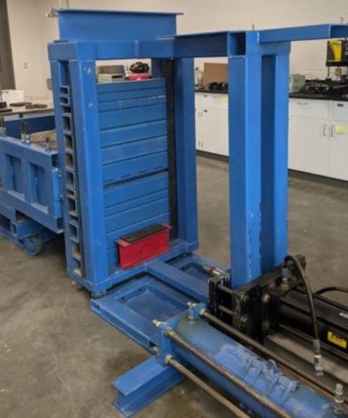
Schematic of Pullout Test Setup
Description
Mechanically Stabilized Earth (MSE) is a ground improvement technology that is used to construct earth retaining walls and steep slopes (NCHRP 1987, NHI 2009). MSE is characterized as a composite structure that consists of tensile resisting inclusions and compacted soil. The design of MSE requires that global, external, and internal stability issues be considered. The pullout resistance of a soil-reinforcing element is a function of the type of soil-reinforcing element, soil strength properties, soil density, soil confinement, and the overburden pressure. The pullout tests for a soil-reinforcing element are required to be performed in-situ or in the laboratory using a specially designed soil-box. For laboratory-scale testing, ASTM D6706 – Standard Test Method for Measuring Geosynthetic Pullout Resistance in Soil is typically followed.
Specifications
Soil Box:
- Inside plan dimension = 450 mm (18 in.) wide x 1500 mm (60 in.) long x 375 mm (18 in.) deep
- Exit gate consists of a series of 50 mm x 50 mm (2 in. x 2 in.)
- The cross diaphragm can be inserted inside the soil-box to create chambers of varying lengths
Reaction Frame:
- The Closed-Mount reaction frame consists of a 12 mm (½ in.) thick structural steel plate having an area equal to the opening of the soil-box plus 100 mm in all directions. When the pneumatic diaphragm is placed in the box and inflated, it pushes back on the 12 mm (½ in.) thick structural steel plates and the surface of the compacted soil. The pressure inside the pneumatic diaphragm dictates the load that is applied to the surface of the soil inside the soil-box.
- The Elevated-Mount consists of structural steel tubing and 19 mm (¾ in.) high strength all-thread rods, washers, and nuts. Included in the Elevated-Mount system are two 12 mm (½ in.) structural steel plates that are slightly smaller than the plan surface of the soil-box. The plates are fabricated in such a way that there is a 25 mm (1 in.) gap between the edge of the soil-box and the edge of the plate.
Horizontal Load Frame
- The horizontal load frame consists of welded 50 mm x 100 mm x 6 mm (2 in. x 4 in. x 1/4 in.) structural steel tubing. The horizontal load frame is used to mount the hydraulic actuator that is used to apply the horizontal load to the soil-reinforcement.
Hydraulic Load System
- The horizontal load system consists of a two-way hydraulic cylinder. The hydraulic cylinder used in the test program consisted of a body with a 125 mm (5 in.) bore and a 50 mm (2 in.) threaded rod. The maximum extension force of the hydraulic cylinder using 21 MPa (3000 psi) line pressure is equal to 260 kPa (58,000 lbf).
Hydraulic System
- The hydraulic system consists of a power unit, flow controls, and the hydraulic actuator. The power unit consists of a motor, hydraulic pump, and reservoir. The hydraulic system is placed in-line with a chiller, which is used to cool the hydraulic fluid that is returned to the system before it is pumped back into the reservoir.
Position Sensors
- There are two different position transducers used with the pullout soil-box. These include a Linear Variable Differential Transformer (LVDT) and a wire-rope potentiometer.
Inflatable Pneumatic Diaphragm
- The inflatable pneumatic diaphragm was specifically manufactured for this application. The inflatable pneumatic diaphragm was manufactured to have flat sides to prevent binding in the soil-box. The profile of the inflatable pneumatic diaphragm was manufactured in such a way that it was less than the plan area of the soil-box chamber.
Data Acquisition System
- The data accusation system consists of Campbell Scientific components and software programs. The datalogger consisted of a CR10X Wiring Panel.
Publication
- Taylor, Thomas Patrick. “Framework for Determining the Pullout Resistance of Inextensible 2-Wire Soil-Reinforcing Elements Embedded in Sand.” PhD diss., 2018.


